FR4 Material Properties: Electrical, Thermal and Mechanical
Impedance calculations and thermal margin checks often start from a material callout as short as “FR4, Tg 170.” Design discussions tend to stop at that label and the headline values on a datasheet. Board behavior, though, depends on the specific laminate behind the label and the resin content of each layer, and every datasheet value carries its own test conditions. In stripline measurements presented at IPC Expo 1999, lowering the resin content of a single high-Tg FR4 laminate raised its dielectric constant by more than 10%.
- FR4 material properties include moderate dielectric loss, low thermal conductivity and high in-plane stiffness, with exact values that vary by grade.
- Dielectric constant (Dk) and dissipation factor (Df) shift with frequency and with each layer’s glass-to-resin ratio, so impedance and loss models need construction-specific values.
- FR4 is commonly graded by glass transition temperature (Tg). Its long-term temperature rating is the relative thermal index (RTI), which is 130°C for one supplier’s standard-, mid- and high-Tg grades alike.
- Three common FR4 grades absorb 0.18–0.3% water by weight in immersion tests. Absorbed moisture raises Dk and Df and adds delamination and conductive anodic filament (CAF) risk.
- Supplier typical values, IPC-4101 limits and stackup design values are not interchangeable. The IPC-4101 /21 sheet, for example, has a long-standing Dk ceiling of 5.4 at 1 MHz.
What Is FR4 Material?
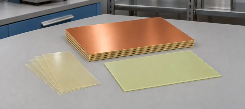
FR4 is a flame-retardant laminate made of woven E-glass fabric bonded with epoxy resin, and it is the most widely used base material for rigid printed circuit boards. A multilayer board combines two forms of FR4. Copper-clad cores are supplied fully cured. Prepreg, a glass fabric impregnated with partially cured resin, bonds the cores together during lamination.
The name FR4 comes from a NEMA grade designation, written FR-4 in NEMA, IPC and UL documents and FR4 in most everyday use. “FR” stands for flame retardant. The “4” is a grade number in a NEMA series that also includes FR-2, FR-5 and G-10, and it carries no flammability rating of its own. Flammability is classified separately under UL 94, and mainstream FR4 laminates carry a V-0 rating.
Most of the properties covered in this article depend on three ingredients:
- Woven E-glass (electrical-grade glass) fabric provides in-plane stiffness and dimensional stability. Its style, designated by numbers such as 1080, 2116 and 7628 from lightest to heaviest, strongly influences how much resin each layer carries.
- The resin system includes the epoxy chemistry, the curing agent and any fillers. It sets glass transition temperature (Tg), decomposition temperature, through-thickness expansion and moisture uptake.
- The flame retardant is brominated in most standard FR4. Grades that must meet halogen-free requirements use alternatives such as phosphorus compounds.
Each ingredient varies from product to product. FR4 is a family of materials, not a single one. IPC-4101, the base-material specification for rigid and multilayer boards, sorts FR4 laminates into specification sheets, often called slash sheets. One laminate frequently qualifies to several sheets at once. A drawing note that reads only “FR4, Tg 170” can therefore cover laminates that still differ in expansion, loss and moisture uptake.
Typical FR4 Property Values by Grade
The table below draws on Isola’s DE104, IS400 and IS410 datasheets, which cover standard-, mid- and high-Tg grades. Each figure is a typical value for that product, measured by the method its datasheet lists. Dk and Df are shown at 100 MHz, the one frequency all three datasheets report.
| Property | DE104 Tg 135°C | IS400 Tg 150°C | IS410 Tg 180°C |
|---|---|---|---|
| Tg, differential scanning calorimetry | 135 | 150 | 180 |
| Decomposition temperature, Td | 315 | 330 | 350 |
| Time to delamination at 260°C, T260 | 12 | >60 | 50 |
| Z-axis coefficient of thermal expansion (CTE), pre-Tg / post-Tg | 70 / 250 | 50 / 250 | 55 / 250 |
| Z-axis expansion, 50–260°C | 4.2 | 3.3 | 3.5 |
| Thermal conductivity | 0.36 | 0.36 | 0.5 |
| Relative thermal index, RTI | 130 | 130 | 130 |
| Dk at 100 MHz | 4.46 | 4.00 | 3.96 |
| Df at 100 MHz | 0.020 | 0.020 | 0.0149 |
| Moisture absorption | 0.3 | 0.18 | 0.20 |
| Peel strength, standard-profile copper after thermal stress | 1.58 | 1.45 | 1.23 |
| Flexural strength, length / cross | 579 / 450 | 565 / 459 | 570 / 458 |
Decomposition temperature rises with Tg across the three columns, but Z-axis expansion and delamination time do not. The mid-Tg IS400 expands less than the high-Tg IS410, 3.3% versus 3.5%, and takes longer to delaminate at 260°C. Both properties depend on the resin system as well as on Tg. IS410’s lower Dk also reflects its specific resin formulation.
Electrical Properties Behind Impedance and Signal Loss
Dk and Df describe how FR4 behaves as a signal medium. Dk, also called relative permittivity, largely sets how fast a signal travels. Together with trace width, copper thickness and dielectric thickness, it determines trace impedance. Df, or loss tangent, indicates how much of the signal’s energy the laminate turns into heat. Electric strength through the thickness, often called dielectric strength, is 44 to 54 kV/mm in the three Isola datasheets and rarely limits a low-voltage board.
Dk and Df Across the Frequency Range
The 1 MHz figure at the top of many datasheets usually overstates Dk for gigahertz signals. For the laminates cited in this article, Dk sits between about 3.7 and 4.5 from 100 MHz to a few gigahertz, and Df between about 0.015 and 0.024. Across that range, Dk typically decreases as frequency rises, and Df increases. For DE104, Dk falls from 4.46 at 100 MHz to 4.32 at 5 GHz as Df rises from 0.020 to 0.024.
Because dielectric loss grows with both frequency and Df and accumulates along the full length of a channel, it matters most on long high-speed links. When you set up a field solver for controlled-impedance work, use the Dk at the frequencies your design actually runs at. For digital signals the rise time defines that range, and for RF circuits the operating band does.
Why Resin Content Moves the Dielectric Constant
Glass has a higher permittivity than cured epoxy, and the Dk of each dielectric layer varies with its glass-to-resin ratio. Layers made with thin glass styles usually carry more resin per ply and have lower Dk as a result, while constructions with less resin have higher Dk. The core values below come from Panasonic’s R-1755C datasheet and were all measured at 1 GHz by the same method. They show the effect within a single product.
| Core construction | Resin content | Dk at 1 GHz | Df at 1 GHz |
|---|---|---|---|
| 0.06 mm, 1080 × 1 ply | 56% | 4.0 | 0.017 |
| 0.10 mm, 2116 × 1 ply | 46% | 4.3 | 0.015 |
| 0.15 mm, 1501 × 1 ply | 42% | 4.4 | 0.015 |
| 0.20 mm, 7628 × 1 ply | 46% | 4.3 | 0.015 |
The resin-rich prepregs in the same datasheet carry 63% to 68% resin, with Dk of 3.7 to 3.8 at 1 GHz. A multilayer board using this laminate and its matching prepreg could therefore mix dielectric layers with Dk values from roughly 3.7 to 4.4. The 2116 and 7628 cores match in both resin content and Dk despite different glass styles.
Resin content also varies across the weave itself, the root of what signal-integrity engineers call the fiber weave effect. A narrow trace routed along a resin-rich window between glass bundles sees a slightly different local Dk from a trace running over a bundle. In high-speed differential pairs that difference shows up as intra-pair skew, which spread-glass styles help reduce.
Standard glass weaveRound bundles leave resin-rich windows. The upper trace runs over a bundle and the lower trace over a window, so the two see slightly different local Dk.
Spread glassFlattened, wider bundles leave only narrow resin gaps, so both traces see a more even mix of glass and resin.
Thermal Properties for Assembly and Long-Term Operation
FR4’s thermal properties cover three separate questions: whether the board survives lead-free assembly, how hot it can run for years, and how well it moves heat.
What Lead-Free Reflow Demands From the Laminate
Tg marks the temperature range over which the cured resin softens from a glassy to a rubbery state. Above it, the Z-axis CTE jumps by a factor of three to five, from 50–70 ppm/°C to 250 ppm/°C for the laminates in the table. Copper expands at about 17 ppm/°C, far less than the laminate through its thickness. As the board heats, that CTE mismatch puts the copper barrels of plated through-holes in tension, and the strain rises sharply once the board passes Tg. Below Tg, the glass fabric keeps in-plane CTE at 11 to 16 ppm/°C, close to that of copper.
Resin chemistry explains why laminates with similar Tg can still perform differently. Many standard FR4 systems are cured with dicyandiamide (DICY). Lead-free-compatible laminates often use phenolic curing agents and inorganic fillers, and they generally hold up longer at reflow temperatures and absorb less moisture. Their cured resin is harder and more brittle, though, and peel strength is slightly lower.
The table’s Td and T260 rows show how well each resin resists decomposition and delamination in standardized laboratory tests. In practice, the number of reflow and rework cycles, board thickness and via aspect ratio often matter more than operating temperature in the choice of laminate grade. Each added cycle strains the plated barrels again, and the accumulated fatigue can end in via barrel cracking in high-temperature boards.
Long-Term Operating Temperature and RTI
Does a higher Tg let a board run hotter for years? Not on its own. UL rates long-term heat resistance separately, using the relative thermal index (RTI). RTI is the highest temperature at which a material keeps a specified electrical or mechanical property within limits through long-term heat aging. All three laminates in the table carry an RTI of 130°C, although their Tg values range from 135°C to 180°C.
For decades, UL’s FR-4 classification capped electrical RTI at 130°C. In 2017 UL added the grades FR-15.0 and halogen-free FR-15.1 for laminates that pass long-term thermal aging at 150°C. For continuous operation above 130°C, the laminate’s RTI has to cover the sustained board temperature, including self-heating. If your product needs UL recognition, the board must also stay within the maximum operating temperature (MOT) in the fabricator’s UL listing.
Thermal Conductivity Through and Along the Board
Heat moves far more easily along a board than through it. A worked example in Electronics Cooling puts the difference at about 67 to 1: a modeled four-layer board had an effective conductivity of 17.4 W/m·K in-plane and 0.26 W/m·K through the thickness. The laminate itself conducts just 0.36 to 0.5 W/m·K in the three datasheets, roughly three orders of magnitude below copper. In the model, the copper planes carried nearly all of the sideways heat. With no thermal vias and 0.25 W/m·K assumed for the laminate, the through-thickness figure barely moved from the laminate’s own.
If copper planes and thermal vias cannot spread enough heat from power devices or LEDs, metal-core and ceramic substrates become worth considering.
Mechanical and Physical Properties of FR4
Woven glass gives FR4 high stiffness and strength in the plane of the board, and the flexural strength values in the table rarely limit a design on their own. Copper peel strength, moisture absorption and board flatness come up more often in design decisions.
Strength, Flatness and Copper Adhesion
How far a finished board deflects during connector insertion, in-circuit test probing or enclosure assembly depends mostly on its thickness, unsupported span, cutouts and support positions. The bending strain concentrates at solder joints and in the laminate just under the pads, especially at the corners of large ball grid array (BGA) packages. Cracking in that laminate, known as pad cratering, became more common with lead-free solders and harder laminate resins.
Warpage comes mainly from an asymmetric stackup, uneven copper across the layers and the board’s thermal history through lamination and reflow. For rigid boards, IPC-6012 sets a default bow-and-twist limit of 0.75% when surface-mount components are used and 1.5% otherwise. Your drawing or purchase order can override that default, for example with a tighter limit where large BGAs need it.
Peel strength measures how firmly copper foil bonds to the laminate, and it affects how well pads resist lifting during soldering and rework. Across these three laminates, peel strength after thermal stress falls as Tg rises. For boards likely to see repeated rework, weigh that lower adhesion against the thermal gains of a higher-Tg grade.
How Much Moisture FR4 Absorbs
FR4 absorbs very little water. In a 24-hour immersion test, the three laminates take up 0.18% to 0.3%. Even this small amount affects the board in three ways:
-
Dielectric shift
Because water has a far higher permittivity than the laminate, absorbed moisture raises Dk and Df and shifts impedance and loss on boards used in humid environments.
-
Reflow delamination
During lead-free reflow, absorbed moisture turns to steam inside the laminate and can separate layers. In a study published in Circuit World, test boards delaminated severely during lead-free soldering after soaking at 85°C and 85% RH, the JEDEC level 1 condition. Boards soaked at the milder level 3 condition of 30°C and 60% RH did not.
-
CAF growth
Under bias and humidity, copper can migrate along the glass-resin interface and form conductive anodic filaments (CAF) between holes or traces.
Why Do FR4 Values Differ Between Datasheets?
When two datasheets give different numbers for the same FR4 property, the cause is usually the product, the test method or the kind of value reported. Panasonic’s R-1755C, for example, lists Tg as 135°C by DSC and thermomechanical analysis (TMA) but 155°C by dynamic mechanical analysis (DMA). Each method responds to a different change within the transition range. Products can only be compared using the same test method and, for Dk and Df, at the same frequency.
Supplier datasheets report typical values, and IPC-4101 slash sheets set the limits used for qualification and substitution. Stackup design values apply to one specific construction, once each layer is fixed. In IPC-4101, the /21 sheet for standard FR4 laminate 0.50 mm and thicker has long set requirements that include the limits below.
| Requirement | /21 limit |
|---|---|
| Tg | ≥ 110°C |
| Dk | ≤ 5.4 |
| Loss tangent | ≤ 0.035 |
| Moisture absorption | ≤ 0.80% |
| Flexural strength, lengthwise | ≥ 415 MPa |
| Flexural strength, crosswise | ≥ 345 MPa |
| Dielectric breakdown | ≥ 40 kV |
Typical values sit well inside these limits. All three Isola datasheets, for example, list dielectric breakdown above 50 kV. Because the /21 Dk ceiling is far above typical values, a design that depends on a specific Dk needs more than a sheet number in its fabrication notes.
Where FR4 Properties Reach Their Limits
FR4 suits most digital, power-control and industrial boards. A design may need a different FR4 grade or another substrate when dielectric loss, sustained temperature, heat spreading or flexibility becomes the limiting requirement.
| Design requirement | FR4 property that becomes the constraint | Typical material choice |
|---|---|---|
| Long high-speed channels, RF and microwave circuits | Dielectric loss at the operating frequency; Dk stability and weave effects | Low-loss epoxy systems that process like FR4, or hydrocarbon-ceramic and PTFE RF laminates |
| Multiple lead-free reflow cycles, thick boards with many layers | Td, T260, Z-axis expansion | Mid- or high-Tg FR4 with lower Z-axis expansion |
| Continuous operation above 130°C | RTI | FR4 listed at 150°C (FR-15.0 or FR-15.1) or polyimide |
| Concentrated heat from LEDs or power devices | Low laminate thermal conductivity | Metal-core (aluminum) or ceramic substrates |
| Repeated flexing or folded installation | Rigid woven-glass construction | Polyimide flexible circuits and rigid-flex boards |
Designers can often stay with FR4 by choosing a lower-expansion grade for reflow, spread glass for skew, or heavier copper planes and more thermal vias for heat. A hybrid stackup can also use RF laminate beneath selected signal layers and FR4 everywhere else.
FR4 PCB Fabrication and Stackup Support
PCBAIR builds FR4 boards from prototype through volume production. Its engineering team reviews your design files, impedance targets and assembly profile, then drafts a stackup that lists the construction and Dk of every dielectric layer. Laminate options cover standard, mid- and high-Tg FR4, including halogen-free and high-CTI (comparative tracking index) grades, from suppliers such as ITEQ, Shengyi and Panasonic.
With fabrication and assembly on one site, finished boards can go to reflow without a long storage gap. Send your Gerber files and drawing notes, and we will reply with a proposed stackup and quote.
Frequently Asked Questions
Is FR4 electrically conductive?
No. FR4 is an electrical insulator. Current in a PCB flows through the copper traces, planes and plated holes, and the laminate keeps them electrically isolated. Leakage on FR4 boards usually comes from surface contamination, absorbed moisture or filament growth between conductors.
Does FR4 melt when heated?
As a thermoset, FR4 softens through the glass transition but does not melt and flow like a thermoplastic. With enough heat the resin decomposes instead. For the laminates in this article, Td (the temperature at 5% weight loss) is above 300°C, though blistering and delamination can start well below that.
Does lead-free assembly require high-Tg FR4?
Not always. Common tin-silver-copper (SAC) lead-free solder begins to melt at about 217°C, and reflow peaks can reach 260°C. Both are above the Tg of standard, mid- and high-Tg FR4. Thicker multilayer boards and repeated reflow or rework favor grades with lower Z-axis expansion and longer time to delamination.
Is FR4 the same as fiberglass or G10?
Fiberglass refers only to the glass reinforcement, while FR4 is woven glass fabric bonded with flame-retardant epoxy. G-10 uses the same construction without the flame retardant and is sold mostly as unclad sheet for machined insulating parts.
Is FR4 halogen-free or RoHS compliant?
Standard brominated FR4 is not halogen-free, but it can still be RoHS compliant. Its bromine usually comes from tetrabromobisphenol A (TBBPA) reacted into the epoxy, while RoHS restricts only two brominated families, polybrominated biphenyls (PBB) and polybrominated diphenyl ethers (PBDE). Halogen-free FR4 is a separate requirement, defined in IEC 61249-2-21 as no more than 900 ppm chlorine, 900 ppm bromine and 1,500 ppm of the two combined.